
Product Overview
WENC2 is a wireless transmitter-receiver system that carries motor encoder signals in industrial environments. The TX (transmitter) reads encoder inputs on the rotating side, and the RX (receiver) reproduces an identical quadrature signal for the drive — without any software or configuration change on the drive side.
It replaces the encoder cable in applications where pulling cable is difficult or impossible: rotating bobbins, rotary tables, slip-ring systems, multi-axis machines, crane drums, and more.

TX Transmitter Module
Mounted on the motor side, reads encoder signals

RX Receiver Module
Mounted at the drive cabinet, outputs quadrature A/B
How It Works
Read → transmit → reproduce — transparent to your drive
1. Encoder Reading (TX)
TX module reads the encoder A/B differential signals on the motor side with opto-isolated inputs.
2. Wireless Transmission
Data is sent peer-to-peer on the 5 GHz band with CCMP encryption and automatic channel hopping.
3. Signal Reproduction (RX)
RX regenerates identical HTL quadrature A/B at supply-tracking level. The drive sees a "real" encoder.
Key Features
Model Options
Three variants, same wireless infrastructure
WENC2-S
Single Encoder (MONO)
- 1 encoder channel (A/B)
- 5 GHz wireless communication
- TX: 1x 8-pin terminal
- RX: 1x 8-pin terminal
- Web interface
- 2nd encoder channel
- 3rd encoder channel
WENC2-D
Dual Encoder (DUO)
- 2 encoder channels (A/B)
- 5 GHz wireless communication
- TX: 1x 8-pin terminal
- RX: 1x 8-pin terminal
- Web interface
- 3rd encoder channel
WENC2-T
Triple Encoder (TRI)
- 3 encoder channels (A/B)
- 5 GHz wireless communication
- TX: 2x 8-pin terminal
- RX: 2x 8-pin terminal
- Web interface
Technical Specifications
5 GHz Multi-Channel
Multi-channel wireless transmission on 5 GHz band, immune to industrial interference
5 GHz3 Encoder Channels
Independent A/B phase inputs, multi-shaft monitoring support
3x A/BIsolated Encoder Supply
Isolated encoder supply output on TX side (+23.5V)
TX OutputWide Supply Range
10..30V DC, short-circuit, over-temperature and over-voltage protection
10~30V DCWeb Interface
Real-time monitoring over 5 GHz multi-channel — RSSI, temperature, 8 live charts
5 GHz APParameters Table
| Parameter | TX (Transmitter) | RX (Receiver) |
|---|---|---|
| Wireless Communication | ||
| Wireless Standard | 5 GHz multi-channel | 5 GHz multi-channel |
| Frequency Band | 5 GHz | 5 GHz |
| Data Protocol | Point-to-point | Point-to-point |
| ACK Rate | — | 89 ~ 100 % |
| Frequency Management | Automatic | Automatic |
| Antenna | External 5 GHz, 1.1 dBi | External 5 GHz, 1.1 dBi |
| Input / Output | ||
| Encoder Input | 3 channels (A/B phase) | — |
| Encoder Output | — | 3 channels (protected) |
| Web Interface | — | 5 GHz AP + HTTP |
| Electrical | ||
| Supply Voltage | 15–32 V DC (nominal 24 V) | 10–32 V DC (nominal 24 V) |
| Encoder Supply (Pin 3) | +23.5 V filtered, 500 mA | — |
| Max Transient Voltage | 40 V (pulse) | 40 V (pulse) |
| Reverse Polarity | Withstands to −32 V | Withstands to −32 V |
| Over-voltage Protection | 35 V varistor + fuse | 35 V varistor + fuse |
| ESD Rating | ±4 kV contact / ±8 kV air | ±4 kV contact / ±8 kV air |
| Power Consumption | ~0.3 W typical | ~0.3 W typical |
| Physical & Environmental | ||
| Enclosure (WxHxD) | 64.50 × 115 × 35 mm | 64.50 × 115 × 35 mm |
| Weight | ~120 g | ~120 g |
| Mounting | TS35 DIN rail + screw | TS35 DIN rail + screw |
| IP Rating | IP20 (higher on request) | IP20 (higher on request) |
| Operating Temperature | −20°C … +60°C | −20°C … +60°C |
| Storage Temperature | −40°C … +85°C | −40°C … +85°C |
| Connector | 2× 8-pin terminal, 3.81 mm pitch | 2× 8-pin terminal, 3.81 mm pitch |
| Conductor | 0.22–0.75 mm² (AWG 24–18) | 0.22–0.75 mm² (AWG 24–18) |
PPR / RPM Coverage
Transparent forwarding — pulse bandwidth scales with encoder PPR
WENC2 is transparent to the drive — it forwards encoder pulses unchanged. Pulse bandwidth is defined over 3600 RPM @ 1024 ppr. The upper RPM limit scales inversely with the pulse rate:
| Encoder PPR | Upper RPM Limit (approx.) | Note |
|---|---|---|
| 512 | 7200 RPM | High-speed applications |
| 1024 | 3600 RPM | Standard reference |
| 2048 | 1800 RPM | High-resolution positioning |
When encoder PPR changes, only the drive parameter is updated. No setting required on WENC2.
Terminal Assignments
TX and RX pinout for all models
TX (Transmitter — Motor Side)
| Pin | Function | Model |
|---|---|---|
| 1 | +24 V supply input | All |
| 2 | GND | All |
| 3 | +23.5 V encoder supply output | All |
| 4 | GND (encoder) | All |
| 5 | ENC0.A | All |
| 6 | ENC0./A | All |
| 7 | ENC0.B | All |
| 8 | ENC0./B | All |
| 9 | ENC1.A | D, T |
| 10 | ENC1./A | D, T |
| 11 | ENC1.B | D, T |
| 12 | ENC1./B | D, T |
| 13 | ENC2.A | T |
| 14 | ENC2./A | T |
| 15 | ENC2.B | T |
| 16 | ENC2./B | T |
RX (Receiver — Drive Side)
| Pin | Function | Model |
|---|---|---|
| 1 | +24 V supply input | All |
| 2 | GND | All |
| 3 | GND | — |
| 4 | ENC0.A | All |
| 5 | ENC0./A | All |
| 6 | ENC0.B | All |
| 7 | ENC0./B | All |
| 8 | GND | — |
| 9 | ENC1.A | D, T |
| 10 | ENC1./A | D, T |
| 11 | ENC1.B | D, T |
| 12 | ENC1./B | D, T |
| 13 | ENC2.A | T |
| 14 | ENC2./A | T |
| 15 | ENC2.B | T |
| 16 | ENC2./B | T |
Note — 2-wire encoder: Only A and B are connected. On the TX side, /A and /B terminals are bridged to GND. On the RX side no bridging is done.
Connection Diagrams
Wiring schematics for all three models
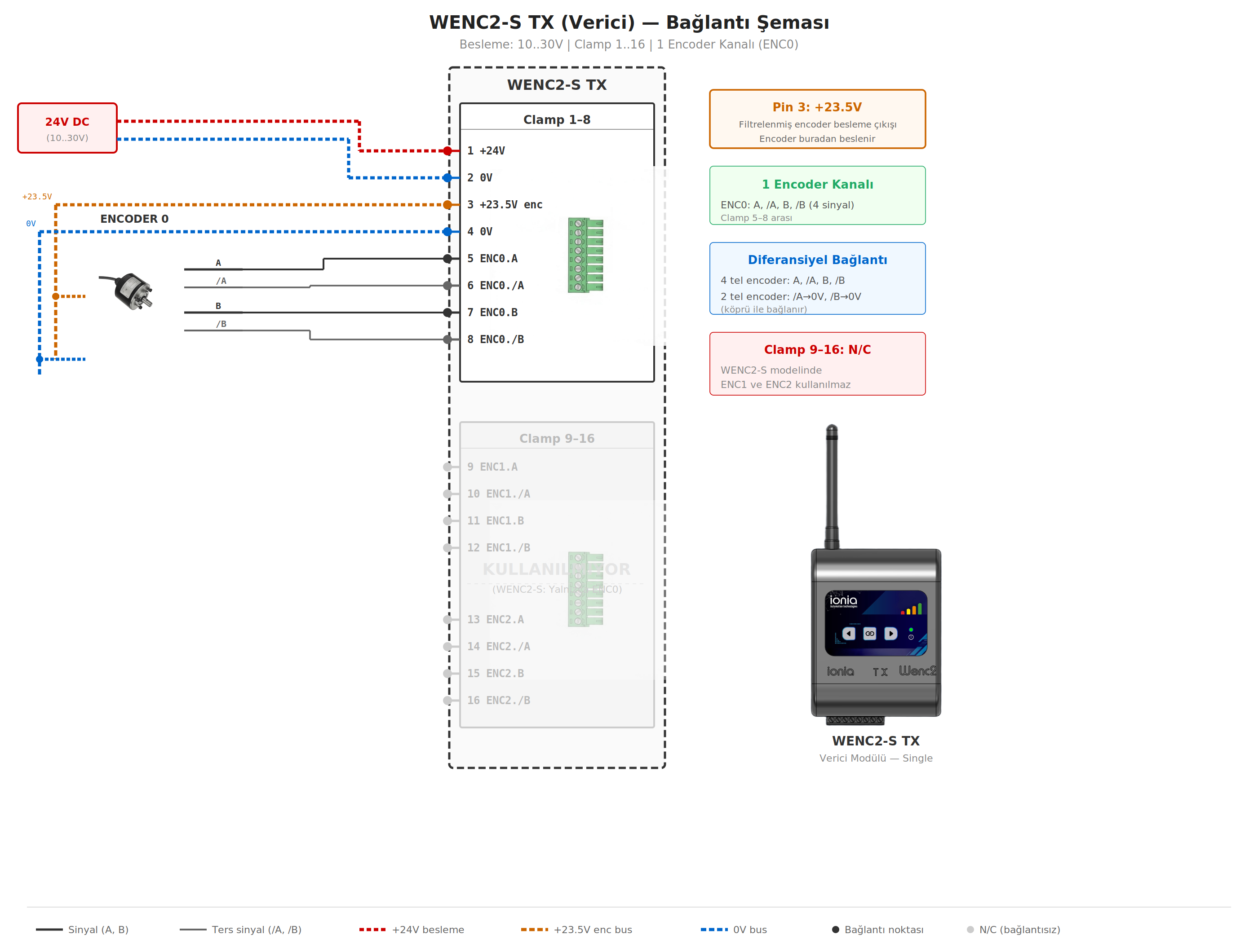
WENC2-S TX
Single encoder, transmitter side
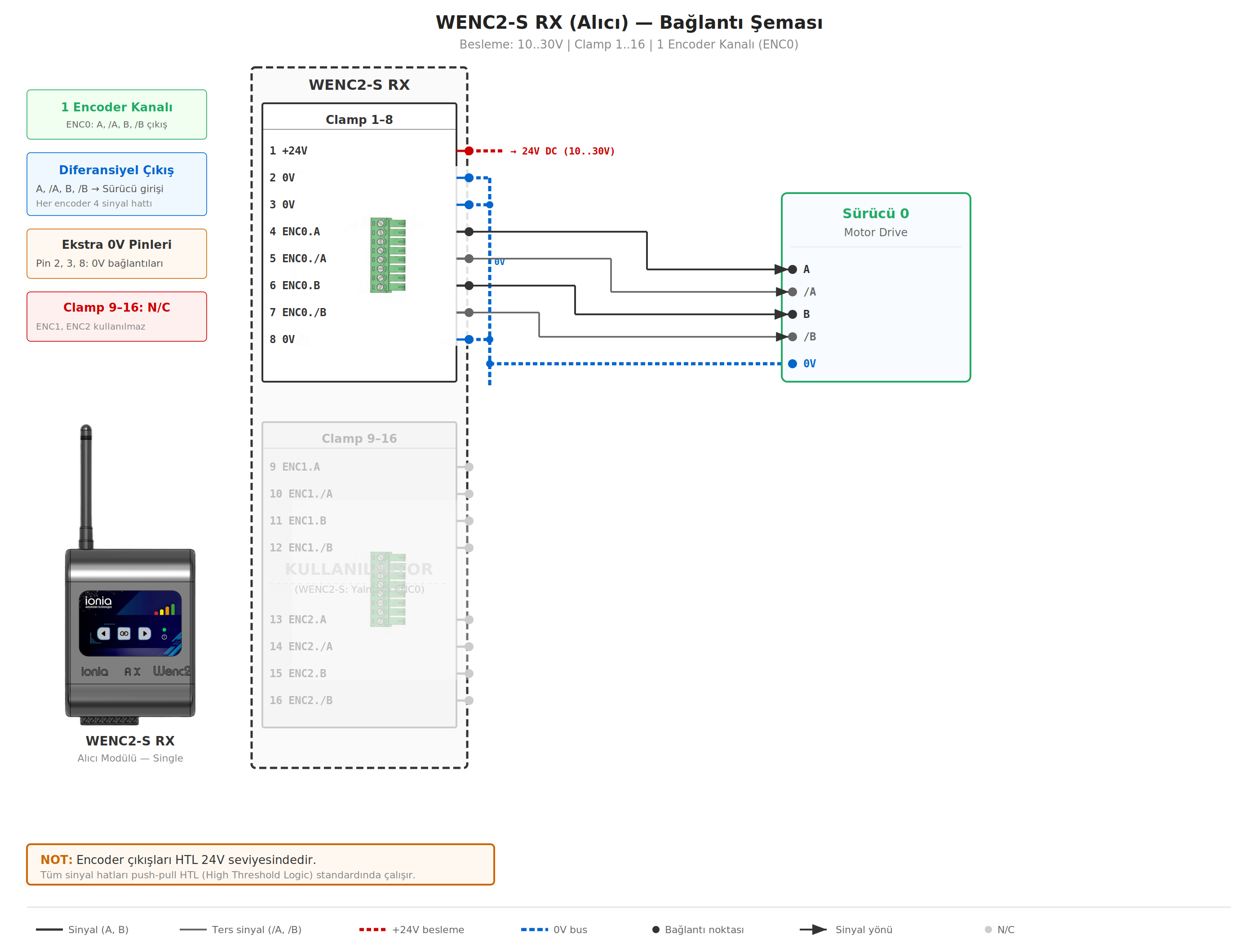
WENC2-S RX
Single encoder, drive side
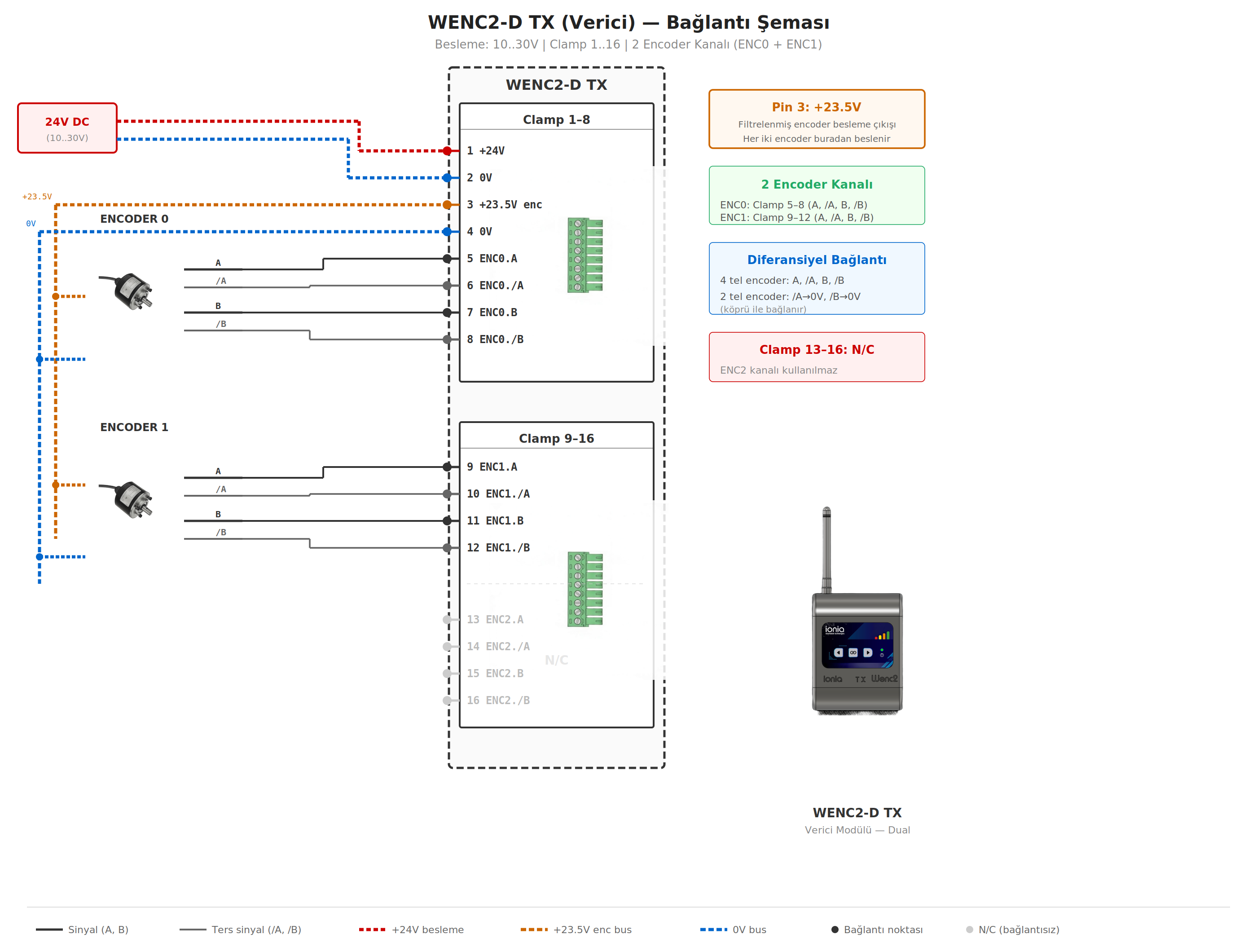
WENC2-D TX
Dual encoder, transmitter side
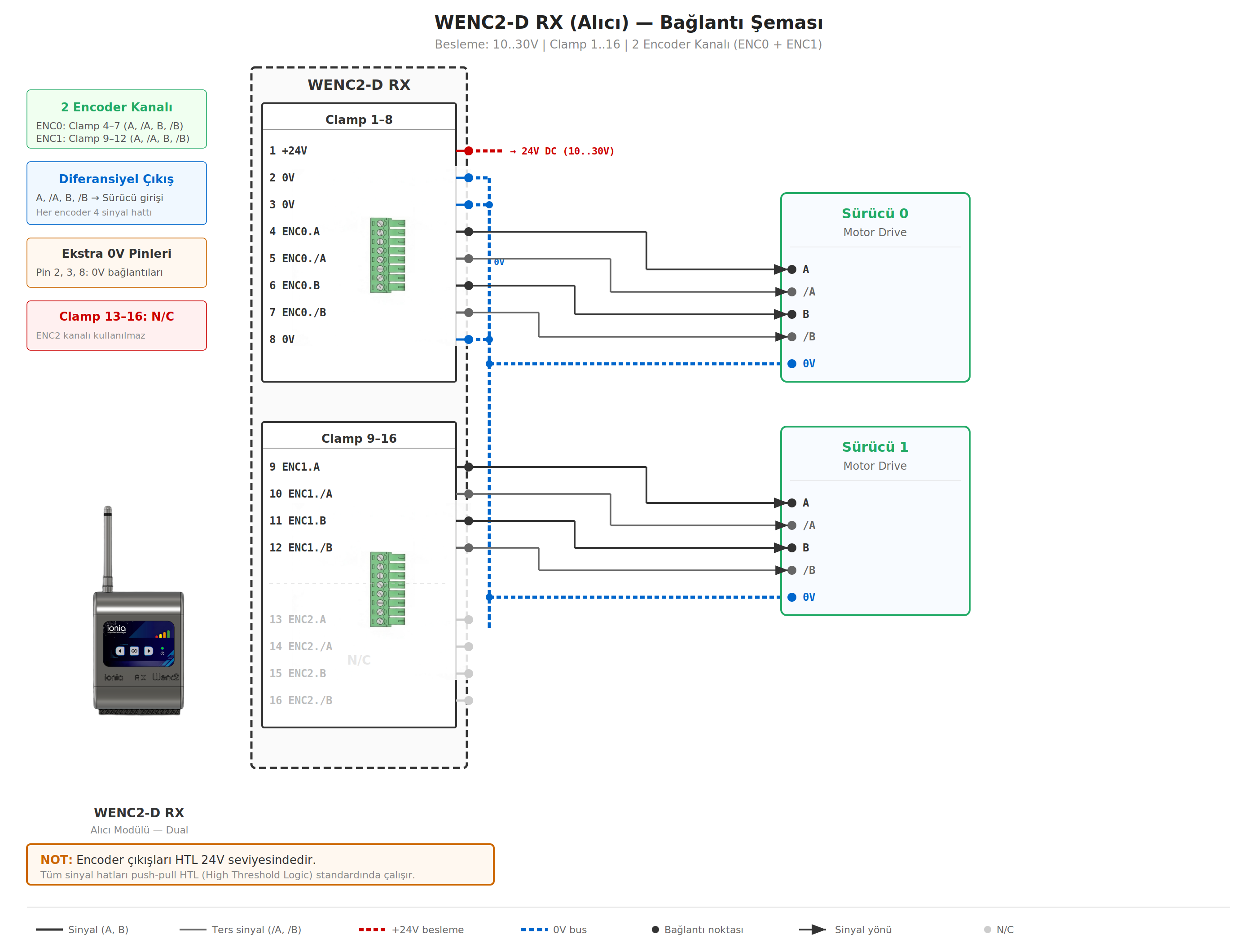
WENC2-D RX
Dual encoder, drive side
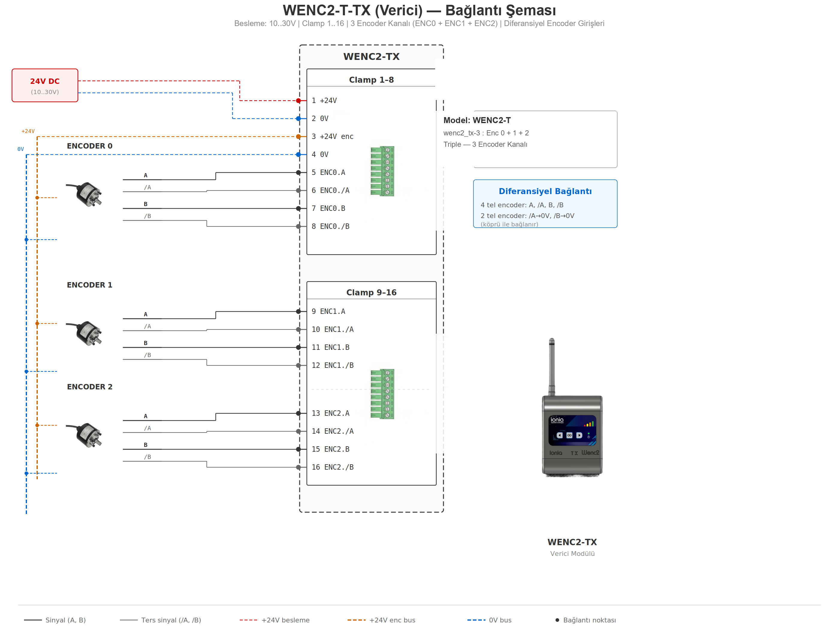
WENC2-T TX
Triple encoder, transmitter side
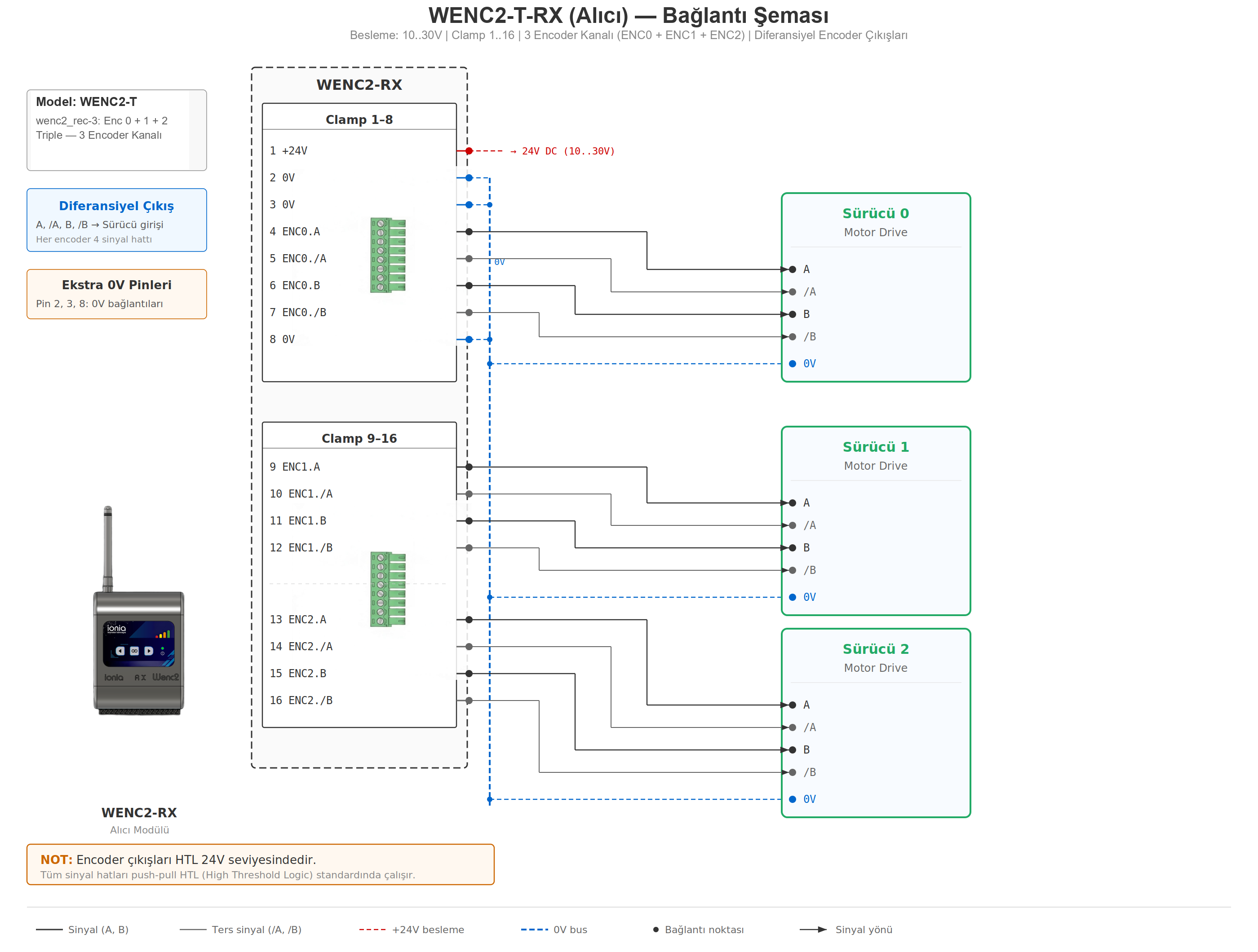
WENC2-T RX
Triple encoder, drive side
Web UI (Service Mode)
Pair, monitor, diagnose and update — from any tablet or phone
Live Monitoring
Real-time encoder rotation animation per channel. Instant RPM, Hz, direction (CW/CCW/Stop), RSSI with dBm value.
A/B Signal Diagnostics
Colored indicators show A and B signal levels. Green = HIGH, Red = LOW. Detect broken cables and wiring faults visually.
Pairing & Locate
Scan nearby TX units, create persistent pairing. "Locate Me" flashes device LEDs for 5 s to identify physical unit.
Restart Counter
Tracks short power interruptions. High TX count → poor slip-ring contact. High RX count → drive-side supply problem.
OTA Firmware Update
RX direct update. TX firmware uploaded wirelessly via RX proxy. Model compatibility checked automatically. Failed uploads roll back.
System Info
CPU temperature, firmware version & date, MAC addresses, last reset reason — both TX and RX visible at a glance.
Operating Modes
Normal Mode
Paired devices auto-connect on power up. Encoder data is transmitted in real time. RX reproduces identical quadrature. LEDs show signal strength.
Service Mode
RX opens a WiFi access point. Web UI access from tablet/phone. Live monitoring, pairing, settings and OTA firmware update.
LED Signal Strength
4-bar LED indicator shows real-time RSSI. D4 (25%) @ −85 dBm, D3 (50%) @ −70 dBm, D2 (75%) @ −55 dBm, D1 (100%) @ −40 dBm.
Secure Update (Anti-Rollback)
Automatic Rollback on Failure
After an OTA update, the new firmware must validate itself within 60 seconds. If validation fails (crash, error), the device automatically rolls back to the previous working firmware. Broken updates can never be installed in the field.
Model Compatibility Check
Firmware target model is validated before flash. Uploading wrong-model firmware is rejected — no manual checks needed.
Compliance & Certifications
CE-certified 5 GHz RF module
The wireless layer of WENC2 is based on a CE-certified 5 GHz dual-band RF module.
RF Module Certifications
Currently certified with CE (European Conformity). Additional certifications (FCC, IC, MIC, SRRC, KCC, ANATEL) are in the roadmap and will be added as they are obtained.
Troubleshooting Reference
Quick diagnostic guide
| Symptom | Possible Cause | Solution |
|---|---|---|
| LEDs not lit | No power or no signal | Check supply (10–30 V). LEDs off = no link. |
| Pairing fails | Devices not in service mode | Put both devices into service mode (Knight Rider animation). |
| Web UI doesn't open | Wrong WiFi or mobile data | Connect to SSID WENC_XXXXXX, disable mobile data. |
| Encoder turning but no count | Cable fault or RX in service | Use A/B diagnostics in Web UI. Return RX to normal operation. |
| Direction inverted | A/B order | Invert at drive, or swap A/−A (4-wire), or swap ENC.A/ENC.B on TX (2-wire). |
| All indicators red | Encoder power missing | Check supply; on 2-wire verify /A, /B → GND bridge on TX. |
| Indicators don't change | Broken signal wire | Check corresponding A or B line. |
| Position oscillates ±1 | Wrong wiring | Verify A/B/~A/~B connection order. |
| Frequent restarts | Slip-ring or supply issue | Compare restart counters. TX inc → slip-ring; RX inc → drive supply. |
| Not working after OTA | Broken firmware | Auto-rollback restores previous version within 60 s. |
Order Information
Order Codes
| Order Code | Channels | Contents |
|---|---|---|
| WENC2-MONO (S) | 1 encoder | 1 × TX + 1 × RX pair |
| WENC2-DUO (D) | 2 encoders | 1 × TX + 1 × RX pair |
| WENC2-TRI (T) | 3 encoders | 1 × TX + 1 × RX pair |
Standard Package Contents
- 1 × TX transmitter module
- 1 × RX receiver module
- 2 × external 5 GHz antennas (1.1 dBi)
- 4 × 8-pin 3.81 mm pluggable screw terminal sockets
- Cardboard packaging